2026 Best Dynamic Compaction Equipment for Global Buyers
For global buyers, choosing the best Dynamic Compaction Equipment in 2026 is not a matter of selecting the largest crane or heaviest tamper. The right system must match the ground, the project footprint, and the required improvement depth. FHWA’s Ground Modification Methods Reference Manual (NHI-16-027 and NHI-16-028) explains how soil type, groundwater, impact energy, and treatment layout shape method selection. These details matter on site: a wet fill, a loose granular layer, and a confined urban parcel do not respond alike. Even the best machine cannot compensate for a poor ground investigation.
Louis Menard pioneered dynamic compaction. His work is commonly summarized by this practical principle: apply impact energy to suitable ground to improve its engineering performance. This is a paraphrase, not a verified verbatim quotation. That distinction matters when equipment claims sound certain. Buyers should compare drop-weight capacity, crane stability, cycle time, monitoring systems, service access, and local parts support—not headline specifications alone. Look for documented project results and independent geotechnical verification. Check the details.
This guide evaluates equipment for varied project conditions and buyer priorities, drawing on established engineering guidance rather than unsupported rankings. No single model is best everywhere. Some selection criteria may also be easy to overlook, especially maintenance logistics and noise constraints near occupied sites. We examine those trade-offs directly, so procurement teams can ask sharper questions before committing capital.
Dynamic Compaction Basics: Typical 10–40 t Rams and 10–30 m Drop Heights
2026 Best Dynamic Compaction Equipment for Global Buyers
Dynamic Compaction Basics: Typical 10–40 t Rams and 10–30 m Drop Heights
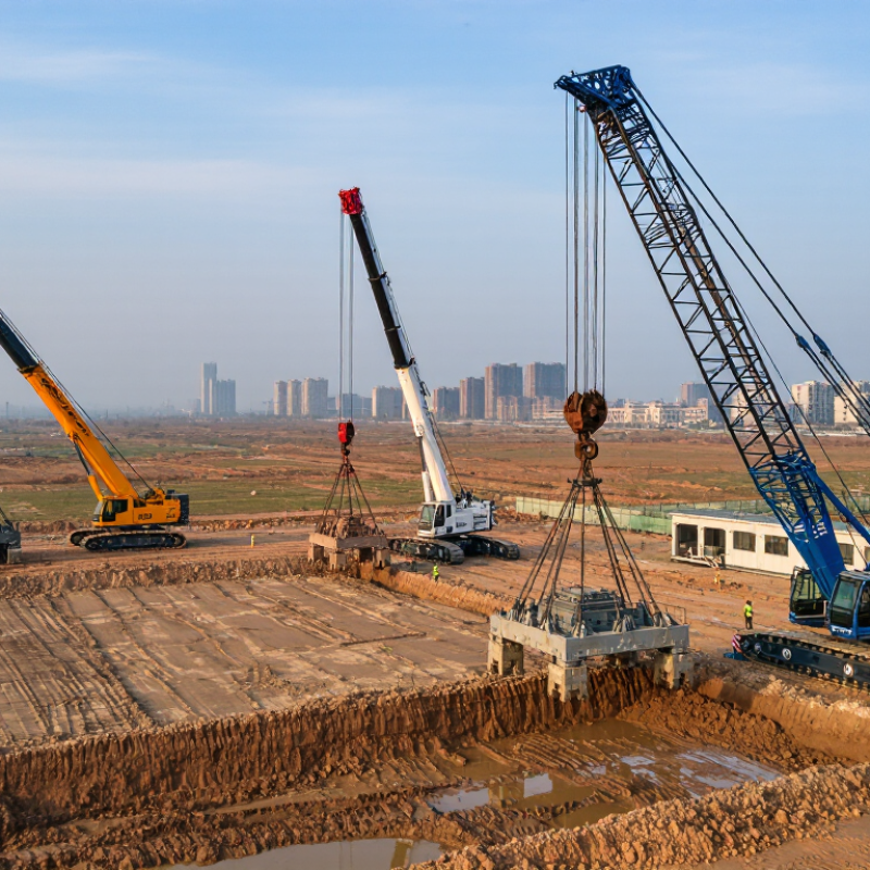
Dynamic compaction densifies loose ground by repeatedly dropping a heavy steel ram. Typical equipment uses 10–40 t rams and drop heights of 10–30 m. These figures describe a broad operating range, not a universal recipe. A 20 t ram dropped from 20 m delivers substantial impact energy, but soil response depends on more than energy alone. Grain size, moisture, groundwater, fill thickness, and nearby structures all influence the result. Crews mark an impact grid, record crater depth, and adjust the sequence when settlement varies. Small changes matter.
Tips: Check groundwater and buried utilities before setting the drop pattern. Keep people outside the controlled impact area, and monitor vibration near sensitive structures. Record ram mass, drop height, and crater response for each pass. Measure, then adjust.
A specification sheet can look tidy while actual ground conditions remain messy. Trial drops help confirm whether the planned energy suits the site. Very high drops may increase vibration or create deep craters, while lighter settings can require more passes. The best setup balances treatment depth, production rate, and surrounding constraints. Engineers should review monitoring results and revise the grid or sequence when field behavior differs from predictions. Even a carefully planned treatment can leave uneven zones, so verification testing remains important before the next construction stage.
Dynamic Compaction Basics: Theoretical Impact Energy
Typical equipment uses 10–40 t rams and drop heights of about 10–30 m. This chart compares theoretical impact energy for different ram masses at a fixed 20 m drop height.
Calculated using E = m × g × h, with g = 9.81 m/s². These values are theoretical gravitational potential energy; actual energy transferred to the ground varies with site and equipment conditions.
Site Screening: Granular Soils and Common Improvement Depths of 5–10 m
2026 Best Dynamic Compaction Equipment for Global Buyers
Dynamic compaction can suit loose granular soils when the target improvement depth is about 5–10 m. Start with a site investigation, not an equipment shortlist. Boreholes or cone penetration tests can help reveal loose layers, dense seams, and groundwater levels. Clean sands and gravels often respond well, while silty or clay-rich layers may limit energy transfer. Conditions vary sharply across a site. A single test point can miss a weak pocket.
Plan trial drops before full production. Record drop height, tamper weight, spacing, crater depth, and ground movement. Watch for excessive vibration near buildings, buried services, or sensitive structures. If groundwater sits close to the surface, pore pressure and drainage need careful review. Improvement depth is an estimate, not a guarantee; verify results with post-treatment testing. The first grid is rarely perfect, so adjust spacing and energy when field data disagree with the design.
Tips: Keep a simple drop log, and photograph the surface after each pass. Check for heave between craters. Small changes matter. Don’t treat a neat crater pattern as proof of uniform improvement; testing should confirm the ground response.
2026 Equipment Comparison: Match Crane Duty to About 1–12 MN·m Impact Energy
Dynamic compaction buyers should compare impact energy with crane duty, not treat the MN·m figure as a complete equipment specification. The FHWA Ground Improvement Methods Reference Manual (NHI-06-019/020, 2006) describes tamper masses of about 5–30 tonnes and drop heights of 10–30 metres. Using E = mgh, that corresponds to roughly 0.5–8.8 MN·m per drop. A 1–12 MN·m comparison therefore spans routine work and demanding high-energy applications. Check the crane’s rated capacity at the actual working radius, including the tamper, rigging, and operating setup. Radius matters. So does the duty cycle.
At the upper end, 12 MN·m from a 30-metre drop implies a theoretical tamper mass near 41 tonnes, before rigging is counted. Crane selection must follow load charts and the complete lift configuration, not energy alone. Ground conditions also change the practical choice: loose fill, nearby structures, and required treatment depth can alter drop patterns and productivity. Small details matter. A neat energy table can still mislead, because site variability rarely fits clean comparison rows. That comparison is imperfect. Review geotechnical data and trial-drop results before committing to a machine class; the right match is the one that delivers the target energy safely and consistently at the required radius.
Performance Checks: Verify Ground Improvement with ASTM D5778 CPT or D1586 SPT
2026 Best Dynamic Compaction Equipment for Global Buyers
Performance Checks: Verify Ground Improvement with ASTM D5778 CPT or D1586 SPT
Dynamic compaction equipment delivers impact energy, but field verification shows whether the ground responded as intended. Establish baseline conditions before treatment, then repeat tests at planned locations and depths. Keep test points consistent where practical. Small layout changes can make comparisons less useful.
ASTM D5778 cone penetration testing provides a near-continuous profile of cone resistance, sleeve friction, and, when measured, pore pressure. It can reveal soft layers between impact points. ASTM D1586 standard penetration testing provides samples and blow counts at discrete intervals. Account for equipment and procedure, and use energy-corrected N60 values when appropriate. The methods are not interchangeable.
Timing matters. In saturated fine-grained soils, excess pore pressure may need time to dissipate after impacts. Testing too soon can misrepresent improvement. Gravel, cobbles, or variable fill may also obstruct CPT or distort SPT results. Not every site gives a neat answer. Compare results with the project’s specified acceptance criteria, groundwater conditions, and baseline data; do not rely on one isolated high reading. Document coordinates, test depths, dates, and any refusal or unusual response, so the engineer can judge whether more testing is needed.