10 Best CNC Cutting Tools for Precision Machining?
Precision machining depends on more than a powerful spindle or a carefully programmed toolpath. A worn edge can leave a thin burr along an aluminum pocket. A poorly matched insert may chatter against stainless steel, marking a finished surface. These small details matter. Choosing suitable Cnc Cutting Tools helps control accuracy, finish quality, cycle time, and tool life across demanding jobs.
This guide examines ten widely used cutting tool types, from end mills and drills to reamers and thread mills. It considers practical factors such as workpiece material, cutting geometry, coating, rigidity, and chip evacuation. The right choice is rarely universal. A carbide end mill that performs well in a rigid setup may struggle on a long, flexible toolholder. Even sound recommendations need checking against the machine, coolant method, and manufacturer’s cutting data. That part is easy to overlook.
The aim is not to promise perfect results from a tool alone. Setup, maintenance, and operator judgment still shape the outcome. Some recommendations may need adjustment for unusual alloys or older equipment. Use this overview as a starting point, then confirm specifications with reliable supplier guidance and controlled test cuts. A careful trial often reveals what a catalog description cannot.
ISO 513 Classifies Machinable Materials into Six Groups: P, M, K, N, S, and H
10 Best CNC Cutting Tools for Precision Machining?
ISO 513 Classifies Machinable Materials into Six Groups: P, M, K, N, S, and H
The ISO 513 groups help match cutting tools to the material, rather than rank tools from best to worst. P covers steel, M stainless steel, and K cast iron. N includes non-ferrous metals such as aluminum. S covers heat-resistant alloys and titanium, while H refers to hardened materials. Each group behaves differently under the cutting edge. Stainless steel can generate heat and work-harden; cast iron often produces abrasive dust. These differences affect insert grade, edge strength, geometry, and cutting conditions.
Tips: Check the material grade, hardness, and workpiece condition before choosing a tool. For aluminum, a sharp edge can help limit built-up material. For hardened steel, confirm the tool is rated for the actual hardness. Start with recommended cutting data, then adjust carefully while monitoring chips, sound, and surface finish.
The group is a useful starting point, not a complete recipe. Two materials within one group may still cut differently. A long, thin part may chatter even with a suitable tool, while a stable setup may allow faster cutting. I would also verify coolant needs and machine rigidity; these details are easy to overlook. Small details count. Tool selection improves when ISO classification is considered alongside the setup and the finished surface required.
10 Best CNC Cutting Tools for Precision Machining? — ISO 513 Material Groups
A qualitative comparison of common cutting-tool materials across the six ISO 513 workpiece groups.
Scores are a qualitative guide, not measured performance data: 0 = not typical, 1 = limited use, 2 = commonly used, and 3 = especially established. ISO 513 groups classify workpiece materials; actual tool choice also depends on the specific grade, cutting conditions, and operation.
Ten Core CNC Cutting Tools: End Mills, Drills, Inserts, Taps, and More
10 Best CNC Cutting Tools for Precision Machining?
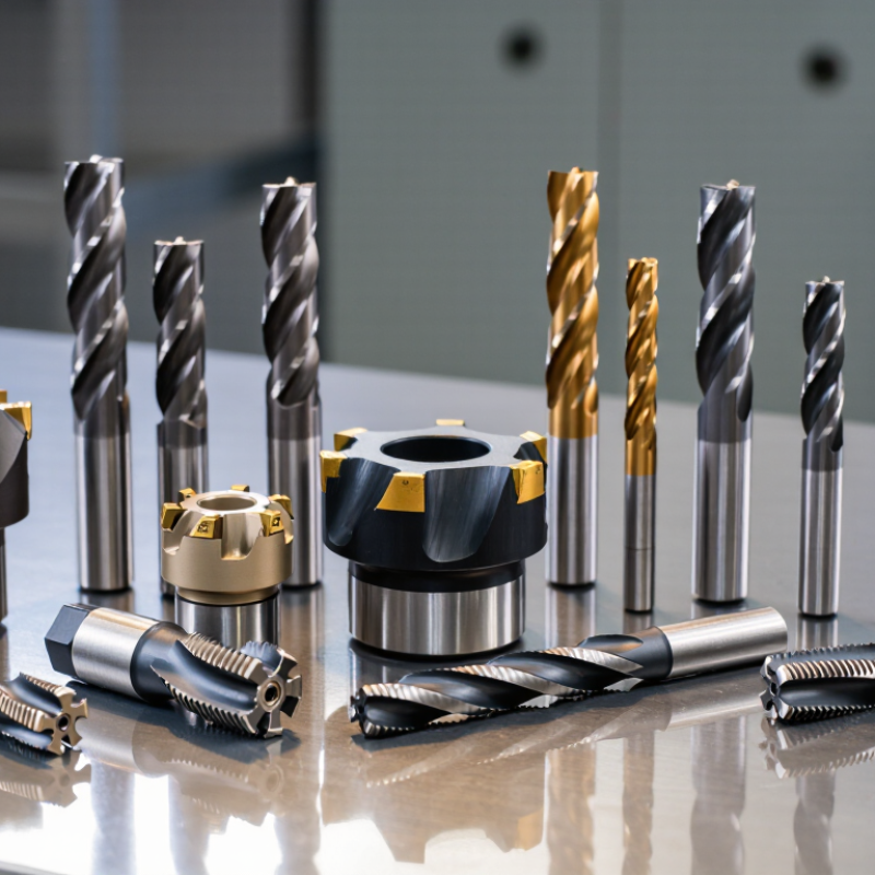
A reliable tool list starts with the cut, not the catalogue. End mills shape pockets and profiles; drills make holes, while reamers refine their diameter and finish. Face mills remove broad layers of material. Boring bars correct existing holes, and indexable inserts support repeatable turning and milling. Taps cut internal threads; thread mills offer a flexible alternative when one tool must cover several thread sizes. Add countersinks and chamfer tools for clean edges, plus slitting saws for narrow slots. Small details matter.
Tool choice affects output across a substantial industry. The U.S. Cutting Tool Institute and AMT reported U.S. cutting-tool consumption of about $2.1 billion in 2023. That figure reflects demand across many operations, not a universal tool recipe. Material, machine rigidity, coolant delivery, and workholding all change what performs well. A carbide end mill may cut hardened steel efficiently, yet chatter on a lightly clamped part. I would check chip shape, spindle load, and edge wear before raising feed rates. More speed is not always better.
For a practical setup, match flute count and geometry to the material, then verify tool reach against the deepest feature. Use a short drill where possible; long drills can wander. Select inserts by workpiece material and cut conditions, and replace them before edge wear damages surface finish. Taps need aligned entry and suitable lubrication. The less glamorous step is often checking runout. A small error at the holder can leave visible marks, even with a sharp tool.
Tool Materials Compared: HSS, Carbide, Cermet, Ceramic, CBN, and PCD
Choosing a CNC cutting tool starts with the workpiece, not the catalogue. ISO 513:2012 sorts machining applications into six groups, including steel, cast iron, non-ferrous metals, and hardened materials. That framework helps narrow the choice, but it does not predict tool life by itself. HSS tolerates shock and is easy to regrind, yet loses hardness as cutting temperatures rise. Carbide suits many production jobs because it balances wear resistance and toughness. Cermet can leave a clean finish in stable turning, but interrupted cuts may chip its edge. Ceramic handles high heat and speed, though it dislikes vibration. CBN is useful for hard ferrous parts; PCD excels on aluminum and other non-ferrous materials, but is unsuitable for ordinary steel cutting.
The differences show up at the spindle. A carbide insert cutting steel may survive a rough, interrupted pass that chips a ceramic edge. On a quiet finishing pass, ceramic can run faster and leave a smooth surface. CBN and PCD are specialist choices, not automatic upgrades. ISO 3685 provides a standardized method for evaluating tool life in turning tests; compare materials under consistent speed, feed, and failure criteria. Real shop results still vary with rigidity, coolant, and setup. I have seen a “better” grade disappoint when the workholding was weak.
Tips: Start with the material group, then test one variable at a time. Check chips, edge wear, and surface finish after each pass. Keep notes. A small trial can save a costly insert—and sometimes reveal that the tool was never the problem.
Cutting Parameters Explained: Speed, Feed, Depth of Cut, and Tool Life
Cutting Parameters Explained: Speed, Feed, Depth of Cut, and Tool Life
Speed, feed, and depth of cut work as a system. A high spindle speed may suit a small carbide cutter, but the same setting can overheat a larger tool. Start with the tool maker’s guidance, then account for workpiece material, tool diameter, and machine rigidity. Small changes matter. For example, a thin-walled aluminum part may vibrate under a deep cut, even when the spindle sounds steady.
Feed rate depends on spindle speed, flute count, and chip load per tooth. If feed is too low, the edge may rub instead of cutting, creating heat and a shiny, damaged surface. Too high, and chips can become thick or the cutter may deflect. Watch the chips. Their shape and color offer useful clues, but they are not a substitute for inspection. A quick test cut on scrap can reveal more than a perfect-looking calculation.
Depth of cut affects both cutting forces and cycle time. Reduce it when a setup is flexible, or increase it cautiously when the workholding is solid. Tool life depends on more than elapsed minutes: inspect for flank wear, chipped edges, built-up material, and changes in sound. There is no universal setting. I still find that a conservative first pass can be slower, yet it often prevents a costly broken tool.
Tool Selection and Testing: ISO 3685 Tool-Life Methods and ISO 13399 Data
Tool Selection and Testing: ISO 3685 Tool-Life Methods and ISO 13399 Data
Choosing among CNC cutting tools requires more than comparing catalog numbers. ISO 3685 describes controlled tool-life testing for single-point turning tools. Keep cutting speed, feed, depth of cut, workpiece material, and coolant conditions consistent. Record flank wear at regular intervals, and define the failure limit before testing. Small details matter. A slightly different workpiece hardness can distort the comparison. ISO 3685 does not automatically cover every milling or drilling test, so match the method to the operation.
ISO 13399 provides a standardized way to describe cutting-tool data, including dimensions and geometry. This makes it easier to compare compatible tool records across systems. It does not certify tool performance or predict tool life. Check that insert shape, corner radius, holder dimensions, and cutting-edge data match the physical setup. In practice, a clean data sheet can still conceal a setup mismatch. I would verify critical dimensions at the machine, not rely on a file alone.
Tips: Run repeated tests, not just one. Photograph the cutting edge under consistent lighting, and note chip shape, surface finish, and vibration. If wear results disagree, check tool setup and material variation before blaming the tool. Keep the test record imperfectly honest: note interruptions, measurement uncertainty, and anything that changed mid-run.