7 Tips for Choosing a Cast Resin Transformer

Choosing a Cast Resin Transformer is a technical decision, not merely a purchase based on price. The right unit must match voltage, load profile, installation conditions, fire requirements, and maintenance expectations. IEC 60076-11 classifies dry-type transformers, while IEEE C57.12.01 defines important insulation and performance requirements. These standards provide a useful starting point.

Market data also shows why careful selection matters. Grand View Research reports continued growth in the global dry-type transformer market, driven by urban infrastructure, renewable energy, and safer indoor installations. MarketsandMarkets identifies similar demand from industrial facilities, commercial buildings, and distribution networks. However, market forecasts vary. They should support decisions, not replace engineering calculations.

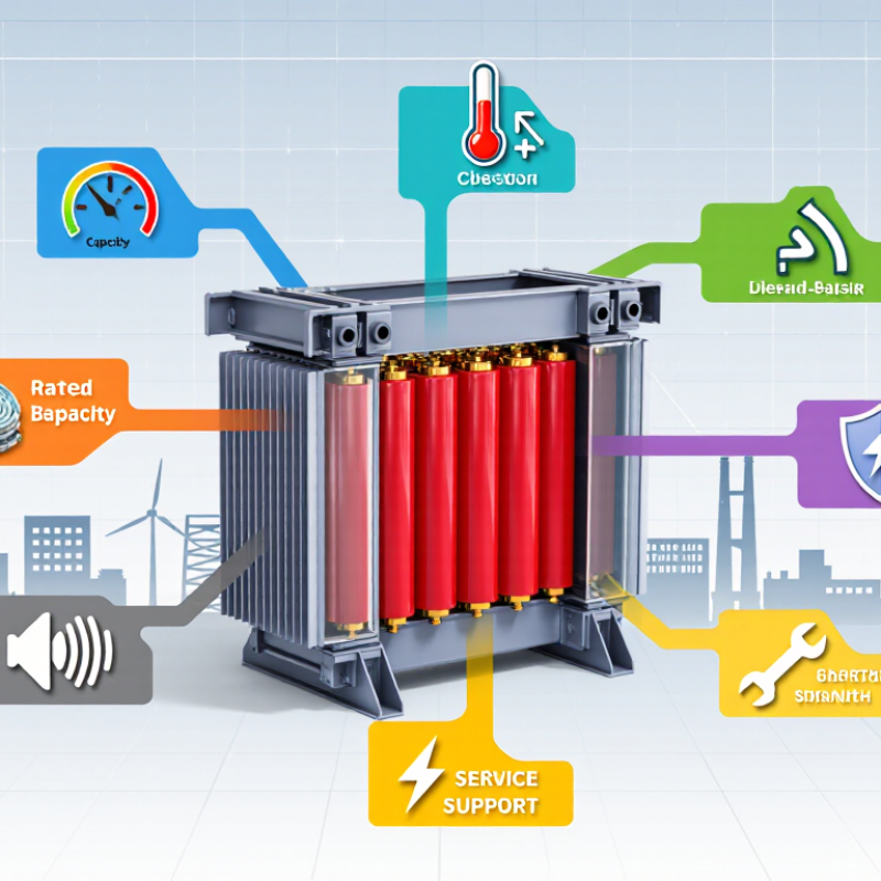
Dr. S. V. Kulkarni, a recognized transformer-design specialist, describes transformer design as “a compromise between electrical, mechanical, thermal, and economic requirements.” That principle remains practical when comparing a Cast Resin Transformer. Look closely at seven areas: rated capacity, overload behavior, insulation class, cooling method, noise level, short-circuit strength, and service support.

Small details matter. A dusty plant may need stronger enclosure protection. A hospital may prioritize low emissions and fire safety. A rooftop installation may require careful temperature and ventilation checks. Ask for verified test reports, not attractive brochures.

The choice is rarely perfect. Engineers must balance efficiency, footprint, price, and future expansion. This guide explains how to compare those factors clearly, while recognizing one uncomfortable truth: the cheapest transformer can become the most expensive equipment in the room.
7 Tips for Choosing a Cast Resin Transformer

Translate Load Demand into kVA: Include Starting and Harmonic Loads

7 Tips for Choosing a Cast Resin Transformer

Tip 1 Start with measured demand, not connected load. Record voltage, phase configuration, power factor, and peak current from site measurements. For three-phase systems, estimate kVA with √3 × voltage × current ÷ 1,000. Include normal lighting, heating, motors, and control equipment.

Tip 2 Treat starting current as a separate requirement. A motor may draw five to seven times its running current during acceleration. This brief surge can cause voltage dips and nuisance trips. Check locked-rotor current, starting frequency, and the largest motor starting point. Soft starters reduce stress, but they do not erase every design concern.

Tip 3 Add nonlinear loads carefully. Variable-speed drives, rectifiers, data equipment, and UPS systems can create harmonic currents. Review the total harmonic distortion and neutral loading. A transformer can carry the calculated kVA and still run hot. That mistake is common.

Tip 4 Apply realistic diversity factors. Do not simply add every nameplate rating, but avoid optimistic assumptions. Production schedules change.

Tip 5 Allow practical growth capacity, often 15 to 25 percent when future loads are uncertain. More capacity is not automatically better; light loading can affect efficiency and project cost.

Tip 6 Check ambient temperature, altitude, enclosure ventilation, and installation clearances. Cast resin units tolerate demanding environments, but heat still matters.

Tip 7 Verify the final selection with a qualified engineer and commissioning data. A neat spreadsheet can still be wrong. Recheck field measurements after installation, especially when motors or electronic loads behave differently than expected.

Check Voltage, Taps, Frequency, and IEC 60076-11 Compliance

Choosing a cast resin transformer requires more than matching its kVA rating. Field experience shows that small specification errors can create heat, noise, or poor voltage regulation.

Tip 1: Verify the primary and secondary voltage under real operating conditions. Do not rely only on nominal values. Tip 2: Check the tap range and tap position. A transformer may need adjustment for long feeder voltage drop. Tip 3: Confirm frequency. A 50 Hz transformer should not be treated as automatically suitable for 60 Hz service. Core flux and temperature can change.

Tip 4: Request IEC 60076-11 compliance evidence. This standard covers dry-type transformer design, testing, insulation, and temperature-rise requirements. A certificate alone is not enough; review the test scope and rated conditions. Tip 5: Compare no-load and load losses. The International Energy Agency reports that global electricity networks lose roughly 8% of generated power, so efficiency deserves attention. Tip 6: Check the enclosure, altitude, cooling, and ambient temperature. A crowded electrical room can quietly reduce thermal headroom. Tip 7: Review harmonics from drives, rectifiers, or data equipment. IEEE 519 is useful for assessing harmonic conditions, although it does not replace transformer-specific testing.

The CIGRE Technical Brochure 673 highlights the importance of insulation aging, partial discharge, and environmental conditions in dry-type transformer reliability. Ask for partial-discharge results and routine-test records. I have seen projects focus heavily on purchase price and overlook ventilation. That decision often needs expensive correction. Some specifications also remain vague, which is uncomfortable but worth challenging before approval.

7 Tips for Choosing a Cast Resin Transformer - Check Voltage, Taps, Frequency, and IEC 60076-11 Compliance

No. Selection Tip What to Check Typical Design Data or Acceptance Criteria Why It Matters
1 Confirm the rated voltage Verify the primary rated voltage, secondary rated voltage, insulation level, and system grounding arrangement. Confirm whether the stated voltage is line-to-line or line-to-neutral. Example: 11 kV primary / 0.415 kV secondary, three-phase, 50 Hz.
The selected transformer voltage must match the system nominal voltage and applicable tolerance.
Incorrect voltage selection can cause excessive core flux, abnormal secondary voltage, poor equipment performance, or insulation stress. The transformer nameplate and drawings should use the same voltage definitions as the electrical system study.
2 Select the correct tap arrangement Check the number of taps, tap range, tap step, tap location, and whether the tap changer is off-circuit or on-load. Confirm that the tap position can be changed only when the transformer is de-energized if it is an off-circuit type. Common example: ±5% in five positions, such as −5%, −2.5%, 0%, +2.5%, and +5%.
Actual tap ranges must be selected from the utility or project voltage-regulation study.
Taps compensate for supply-voltage variation and feeder voltage drop. An unsuitable tap range may leave the secondary voltage outside the required operating window or create unnecessary overvoltage at lightly loaded conditions.
3 Match the operating frequency Confirm the system frequency and ensure the transformer is designed for that frequency. Do not assume that a transformer designed for 50 Hz can always be operated at 60 Hz, or vice versa, without the manufacturer’s confirmation. Typical systems: 50 Hz or 60 Hz.
The nameplate should state the rated frequency, and the volts-per-hertz relationship must remain within the design limit.
Operating at excessive volts per hertz can increase core flux, magnetizing current, losses, audible noise, and temperature rise. Frequency also affects impedance, harmonics, and system compatibility.
4 Size the transformer for the real load Calculate maximum demand, diversity, motor starting current, future expansion, harmonic content, and the required overload profile. Use the actual installation load rather than only the connected-load total. Example calculation: A 1,000 kVA transformer at 415 V, three-phase, supplies approximately 1,391 A at full load:
I = S / (√3 × V).
Undersizing increases winding temperature and reduces service life. Excessive oversizing can reduce efficiency at normal loading, increase inrush effects, and raise purchase and installation costs.
5 Evaluate insulation and environmental conditions Review indoor or outdoor installation, ambient temperature, altitude, humidity, dust, salt contamination, ventilation, enclosure rating, and available clearances. Check whether the cast-resin transformer has the required environmental and climatic performance. IEC 60076-11 classifications may include:
C2: climatic class
E2: environmental class
F1: fire behavior class
Cast-resin transformers are often selected for buildings and demanding environments, but their performance still depends on ventilation, contamination control, temperature limits, and correct installation conditions.
6 Check IEC 60076-11 compliance Request a compliance statement, routine-test records, type-test evidence where applicable, temperature-rise data, partial-discharge results, and the declared insulation system. Confirm the exact edition and scope of the standard used in the project. IEC 60076-11 applies to dry-type power transformers, including cast-resin designs. Typical documentation should identify rated power, rated voltages, frequency, impedance, losses, insulation levels, temperature rise, and test results. A general claim such as “IEC compliant” is not a substitute for documented ratings and test evidence. The project specification should also identify any additional local grid, fire, seismic, acoustic, or installation requirements.
7 Verify installation, protection, and service requirements Confirm transformer dimensions, weight, terminal arrangement, enclosure, cooling method, protection sensors, inrush-current coordination, short-circuit withstand, noise limits, maintenance access, and spare-parts requirements. Typical accessories may include winding temperature sensors, a temperature monitoring relay, cooling fans for AN/AF operation, anti-vibration pads, and an enclosure suitable for the installation area. Correct electrical ratings alone do not guarantee a successful installation. Adequate ventilation, protection coordination, mechanical support, cable bending space, and temperature monitoring help prevent nuisance trips, overheating, and premature failure.

Select Class F Insulation Rated at 155°C and Verify Temperature Rise

Choosing Class F insulation means selecting materials rated for 155°C thermal endurance under IEC 60085. It does not mean the transformer should operate continuously at 155°C. The actual design depends on ambient temperature, loading, ventilation, and winding temperature rise. For a 40°C ambient, a 100 K rise already places the winding near 140°C. That leaves limited margin for overloads, blocked airflow, or uneven cooling. Small details matter. Specify the permitted temperature rise clearly, and request test evidence based on IEC 60076-11. A certificate alone is not enough.

Energy losses make this decision financially important. The U.S. Department of Energy estimated that distribution transformers consume roughly 60 billion kWh annually, representing about 2.5% of national electricity use in its 2016 standards analysis. Lower losses and controlled heat can therefore support both reliability and operating-cost targets. During a technical review, compare no-load losses, load losses, acoustic performance, and the declared temperature-rise test. Do not guess. Check the correction method for ambient conditions and altitude, because laboratory results may not mirror a crowded electrical room. A clean enclosure can still run hot. This is where specifications sometimes look complete but remain vague. Rechecking the hottest-spot assumptions may feel excessive, yet it can expose a small thermal margin before installation.

Apply IEC Site Conditions: ≤1,000 m Altitude and ≤40°C Ambient

7 Tips for Choosing a Cast Resin Transformer

Apply IEC Site Conditions: ≤1,000 m Altitude and ≤40°C Ambient

Check the installation altitude before comparing transformer ratings. IEC 60076-11:2018 defines normal service conditions up to 1,000 metres above sea level. Above this level, thinner air reduces cooling performance and insulation clearances may require engineering review. Tip one: confirm the site elevation. Tip two: request altitude correction data from the manufacturer. Do not assume a standard rating remains unchanged.

Measure the actual room temperature, not only the outdoor forecast. IEC 60076-11:2018 lists 40°C as the maximum ambient temperature, with 30°C as the daily average and 20°C as the annual average. Tip three: inspect summer heat near ceilings and cable trenches. Tip four: verify ventilation capacity. Tip five: leave clear airflow paths around the enclosure. A hot room quietly reduces useful capacity.

Review humidity, dust, and condensation risks. Tip six: select a suitable enclosure and protection level for the environment. Tip seven: require factory test records, thermal data, and site commissioning checks. IEC 60076-1:2011 supports careful evaluation of transformer service conditions and insulation requirements. Field experience shows that small assumptions create large maintenance problems. I have seen room temperatures exceed design expectations because ventilation was treated as an afterthought. Recheck the numbers.

Assess Losses, Noise, IP Rating, and 2-Second Short-Circuit Withstand

Choosing a cast resin transformer requires more than comparing rated power. The following seven checks help connect laboratory data with site conditions.

1. Review no-load and load losses separately. A transformer operating continuously can turn small losses into significant heat and energy costs.

2. Match the design to the real load profile, not only the nameplate rating. Motors, harmonics, and frequent starts can change thermal performance.

3. Ask for measured noise data, including the test distance and operating condition. A quiet unit in a brochure may sound different inside a reflective electrical room.

4. Select the IP rating according to dust, moisture, and cleaning methods. Higher protection is not automatically better; it may reduce cooling or complicate maintenance.

5. Confirm a documented two-second short-circuit withstand capability. Check the tested current, connection arrangement, duration, and applicable standard. Do not accept “high strength” as evidence.

6. Examine routine and type-test records from a competent laboratory. Insulation resistance, partial discharge, temperature rise, and impulse results deserve careful review.

7. Consider installation details, including airflow, clearances, cable access, and service space. I have seen technically suitable transformers perform poorly because ventilation was underestimated. That mistake is easy to repeat.

No checklist is perfect. Review assumptions with the designer, especially when the transformer serves critical loads or operates near its thermal limit.

Build your system. Protect your boat. Join the movement.

Compare Products
Talk to Sales